|
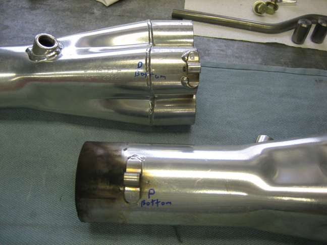
Here you can see what the u-tabs look like on the collectors. Once
you have the header tubes or the tubing reducer inserted, a bolt and
locknut hold the two together. This system works very well but it
doesn't seal 100% as you can see by the exhaust on all the surfaces. On
the other hand, it sure does make it easy to work on. If you look close
you can see a letter D and P on each u-tab. This is so I can tell them
apart once I get them back from ceramic coating.
|
|
 |
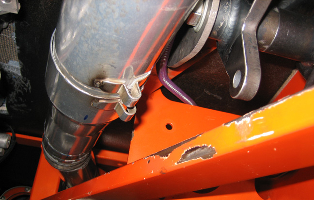
Here you can see the new exhaust system running by the
new bracket and snaking through the chassis. The purple colored plastic
covering has wires in it and will be located against the chassis later.
This pretty much completes the exhaust system except for recoating them
with ceramic coating which I'll be sending out in a day or two. While they're
getting recoated that will give me a chance to work on some other stuff
because coating should take a week or two.
|
|
 |
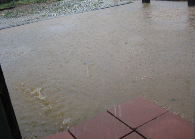
Once I was ready to go in for the day, this is what I had to walk
across. It had been raining most of the day and at times very hard. My
garage is detached from the house which is about 100 feet away so the
floor of the house got a little muddy when I came in. The wind was blowing pretty good
and the temp was in the low 40's while I was working that day with snow
in the forecast for that evening. Sure enough we got a dusting of snow
overnight which was great because we don't get much here in So. Ca. like
we use to. If this keeps up I'll have to put a heater in the garage.
|
|
 |
|
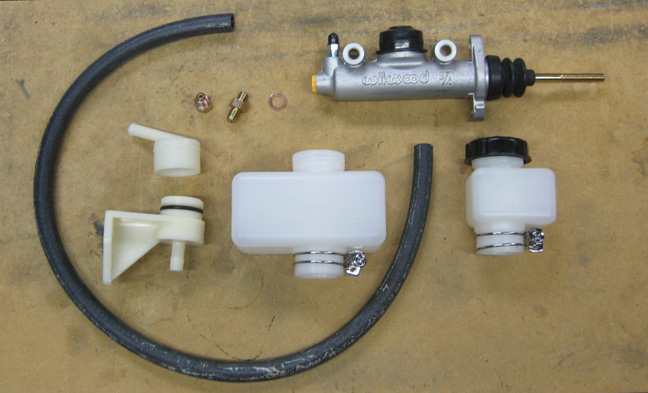
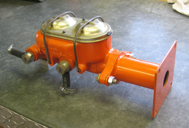
Next I'll be mounting the clutch master cylinder to the chassis. This
one is made by Wilwood and came with the pedals and brackets that I
received from Total Coast Involved awhile back. This is a nice kit and
can be used a few different ways. At the top we have an aluminum master
cylinder with a 3/4" bore. You can mount it to the side of the chassis
through those two holes that you see or from the front with two more
holes that go through the face of it. At the rear is where you run your
line out of and it has a bleeder valve back there too.
Below the master are three different ways of using a reservoir. There
is a large and a small one depending on what kind of clearance issues
you have or you can remote mount your reservoir if you'd like. It comes
with a bracket, hose and some fittings depending on your application.
|
|
 |
|
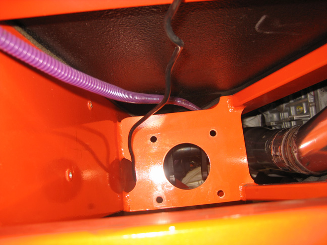
My original plan was to use the two threaded bungs that came with the
kit and weld them to the main frame rail on the left. But after doing
some measuring and thinking, I don't think I'll be doing that after all.
I made a few sketch's of different ways of doing things and I had a hard
time deciding exactly what to do. Once I was happy with one idea,
another one would come to mind and then I'd start down that path. This
happened over and over again so I guess I'm going to wing it here. On
the other hand, there's more than one way to skin a cat. My old brake
master cylinder was mounted to an adapter that I made which bolted to
those four holes in that 1/4" steel plate that you see below. The
pushrod ran through that large hole and worked pretty good for many
years. The reason for that large hole is because my chassis came with a
brake booster for power brakes. I wasn't able to use the power brake
booster back then because someone bought to big of a camshaft which
didn't make enough manifold vacuum to run the booster :-] This is
why I made the adapter in the first place and have been running manual
brakes since day one.
What I finally settled on is making an adapter plate that will bolt
to the bracket below and then mounting both masters to it. One reason
for making this new one is because the clutch pushrod that came with the
kit is shaped like an S and I can't see how to make that work for my
setup. I'll have to make new pushrods once I'm done here but that's no
big deal. Take a good look at this area because it won't look like this
very long.
|
|
 |
Here is my brake master cylinder bolted to the adapter that I was
talking about. The adapter length is the same as the power brake booster
was, in case you were wondering. I decided to keep the adapter but I'll
do a few modifications to it. The adapter is made out of 1/8" thick
steel and is very ridged. I'm not sure how I'm going to fasten it yet
but I'm sure I'll dream up something along the way.
|
|
 |
|
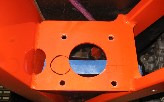
I'm doing some layout here and getting ideas of where I'm going to be
drilling some holes. If you look close you can see a crease in the tape
which is where I drew a line on the other side of it. That line
represents where the two pushrods will end up. What I did was place a
square against the other side of this plate till I had it lined up with
center of the holes in the pedals. Once it was right where I wanted it,
I marked the tape and drew my line across it. Now this is a critical
step because if you get your pushrod out of alignment they won't work
very well. Plus you can get premature wear on your master cylinder which
is a bad thing.
I transferred my line from the other side and started laying out this
side. The dark circle is where the clutch master cylinder will be
mounted and to the right are some layout lines where the brake pushrod
center line will be. I'm kinda stuck with where all these holes will be
drilled because of where the pedals ended up at. I plan on staggering
the two master cylinders with the brake being towards the rear. I
thought this would work best because if they were mounted side-by-side,
it would be very hard to get at and fill the clutch master with fluid
when the brake master was in the way.
The distance between the two masters are at a minimum here which is
3.200" apart. And I had to figure out where to place them from side to
side so both pushrods would run down the side of the mounting points of
the pedals and not in the middle of them. If the pushrod didn't run down
the side of the pedal mounting point, they would end up being at an
angle which again is a bad thing. I gave myself a little extra room here
which means if my calculations are correct, I'll need to make some
spacers to go between the pushrods and pedals later. I'd rather make a
spacer than have an alignment problem.
|
|
|
|
1
2
3
4
5
6
7
8
9
10
11
12
13
14
15
16
17
18
19
20
21
22
23
24
25
26
27
28
|
|
29
30
31
32
33
34
35
36
37
38
39
40
41
42
43
44
45
46
47
48
49
50
51
52
53 |
|
54
55
56
57
58
59
60
61
62
63 |