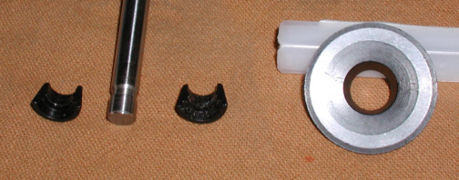
For those that have never seen how the
valve assembly stays together, let me try to explain it. The two tapered pieces are the locks or
keepers. They have a small raised area in the middle of them which fits in the
recessed area of the valve stem. The tapered area on the outside of the
locks mates with the taper on the inside of the retainer on the right. When
the springs are installed, they push upward on the retainer and wedges
the two tapers together. This makes the locks grab the valve stem with
no way to come loose (cross your fingers and knock on wood here). It's
very rare to have valve locks fail so this system works great.
|
|
|
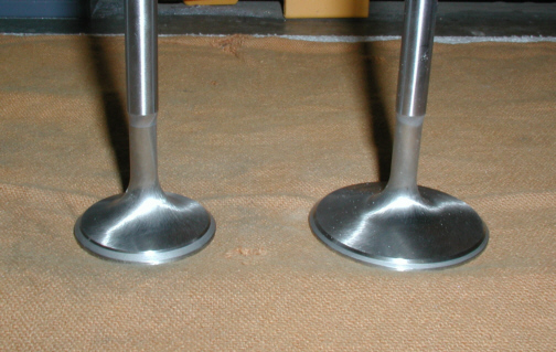
Here we have the exhaust valve on the
left and intake on the right. Notice the reduced area on the stem. This
is for added air flow which is a good thing for
performance. Also notice the surface which has a ground swirl finish.
This aids in air flow as well. Most cars don't have either one of these
features. These are made from stainless steel which takes heat very
well.
|
|
|
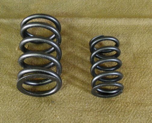
These are the valve springs that I
will be using. Most cars
have only one spring but because I have a roller cam with a lot of lift,
I need to have two of them. This is to make sure the lifters DON'T loose
contact with the cam under high RPM. These springs are rated at 195
pounds at the valve seat....which is a bunch for the street and are
1.550" in diameter (again....very big).
|
|
|
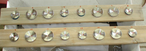
Here is a wooden rack that I made to hold
all the valves. I put numbers next to each hole where the valve goes in
to keep things organized. I'll tell you why it's important to keep these
separated later.
|
|
|
|
1
2
3 4
5 6
7 8
9 10
11 12
13 14
15 16
17 18
19 20
21 22
23 24
25
26 27
28 29 |
|
30
31 32
33 34
35 36
37 38 39
40 41
42 43
44 45
46 47
48 49
50 51
52 53
54
55 |
|
56 57
58 59
60 61
62 63 |