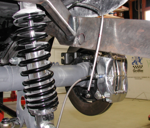
Here you can see how the tubing is on
the other side of the sway-bar hole. I left the tubing long and will
trim it later. Now it's time to make up the other side.
|
|
|
|
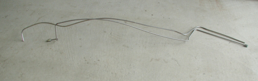
This is what the difference looks like between the
new line and old one. That's only 4" you see there but had to be
done.
|
|
|
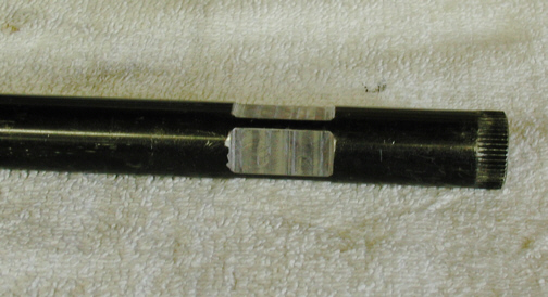
Now that the brake lines are roughed
in, the sway-bar needs to be cut to length. The sway-bar will be
shortened about 1.5" (one .750" per side) and will end up at 31"
long which is the distance from outside to outside of the frame rails. This
is a shot before I cut the bar to show you how the other system worked.
Notice the small splines that go all the way around the diameter of the
bar. This is a very strong way to attach something because of the large
surface area that the splines create. If you were to add up all the
"peeks and valleys" of the splines, you would have a much
greater surface area than just the circumference of
the shaft itself. Think about it!!
|
|
|
|
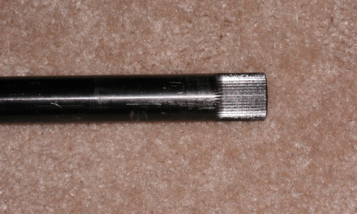
Here you can see the new system and
how it's going to work. After cutting the bar to length, I cut four flats to make a .700" square. Now some of
you may notice that the bar is weaker now. I'll get to that later and
explain the method to my madness. The flats will be used to clamp the
new arms to.
|
|
|
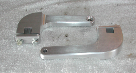
Here are the new arms that I made. You
can see how this is going to fasten now. The depth of the slot is .675"
which will leave a small gap between these two pieces. This way the top clamp will
only clamp the sway-bar. The end of the arm with the 3/8"
diameter hole will be used to attach the adjustable link that goes to the rear-end housing. I used a flathead screw because this will clear
the 4-link bracket better.
|
|
|
|
1 2
3 4
5 6
7 8
9 10
11 12
13 14
15 16
17 18 19
20 21
22 23
24 25
26 27 28 |
|
29 30
31 32
33 34
35 36
37 38
39 40 |