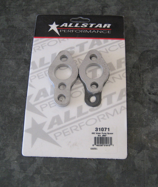
While I'm waiting for parts to come in, I'm going to keep busy again
with other things. What you see here is a spacer for my water pump. When
I built the engine years ago, I used a cast aluminum timing cover but I
didn't realize how thick they really were. After installing my water
pump, the bolts on the back side of it rubbed against the timing cover.
I fixed this by using two sets of water pump gaskets which gave me a
little more room but I never liked doing it this way. I figured while I
had the water pump off the car this time, I could do away with the
double gasket thing and use spacers to do it right.
|
|
|
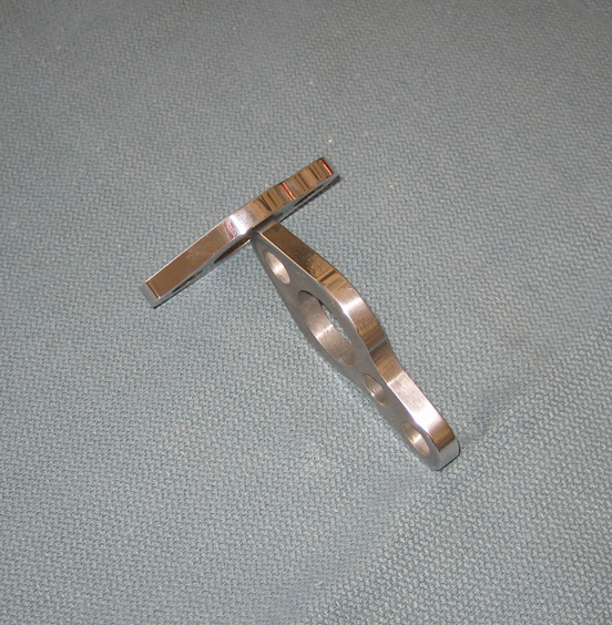
The spacers are 1/4" thick and were raw aluminum but after a few minutes
on my buffer, they were much better looking. This will give me more room
than I need, but it's nice to know that I'll have plenty of clearance
now.
|
|
|
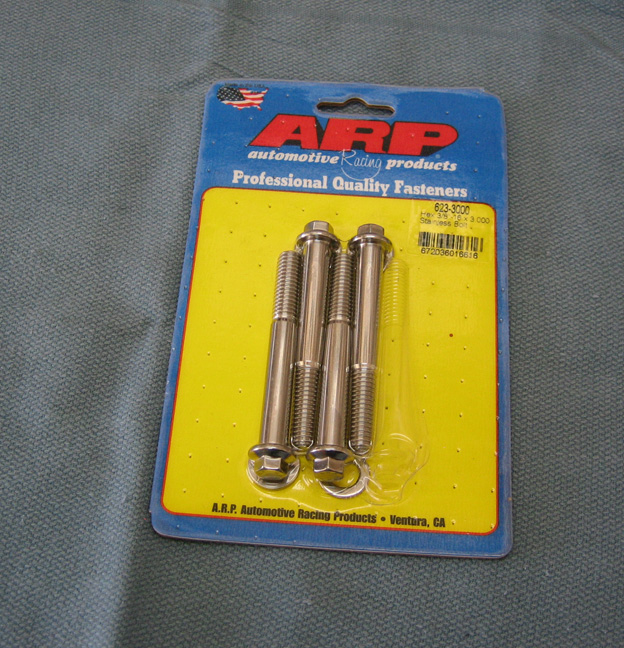
With the longer spacers I'll need longer bolts. Actually I only needed
one bolt here, but you have to buy these in a pack of four. The other
three bolts for the water pump I had laying around but this one had to
be added to the list of parts I needed.
|
|
|
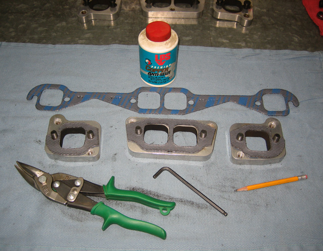
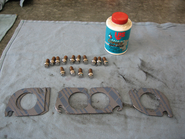
Something else that needed to be done was trimming my exhaust gaskets.
The aluminum adapters that you see below are used when running big tube
headers on a small block Chevy. With the adapters being split into three
pieces, I did the same with my header flanges when I built them years
ago (split them to match the adapters). What I'm doing here is cutting
the gaskets to fit the adapters so it looks nice and clean when the
headers are on. These gaskets go between the adapters and cylinder
heads. There is a layer of steel in the middle of this gasket which
requires tin snips to cut through them.
|
|
|
I'm trimming more exhaust gaskets here but these go between the adapters
and the headers. The bolts that you see are made out of stainless steel
and because they get very hot, I'm using some anti seize on the threads.
This stuff works great and prevents the bolts from sticking in the
threads for years. Before the anti seize was applied, the bolts spent a
little time on the buffing wheel as well.
|
|
|
|
New Pushrods and More Testing
|
4-28-14 |
|
Back to the pushrod and contact patch issue:
To fix this problem I figured I'd need a shorter pushrod but by how
much? After playing with some shims, doing a little math, I came up with
a length. Now I learned something about rocker arm geometry while doing
all this. By changing the distance of the pivot point of the rocker arm,
it changes the rocker arm ratio at the same time. I didn't realize this
at first but after playing with this for awhile, the light come on for
me. I'll talk more about this in a minute.
Anyways, I calculated that I would need a pushrod .075 shorter than
my old ones. But they only come in .050 increments so which one do I
choose, .050 or.100 shorter? I went with .100 shorter and my ace in the
hole was that as long as I only rolled over the motor and didn't start
it, I could send them back for the others if need be. Sweet!!
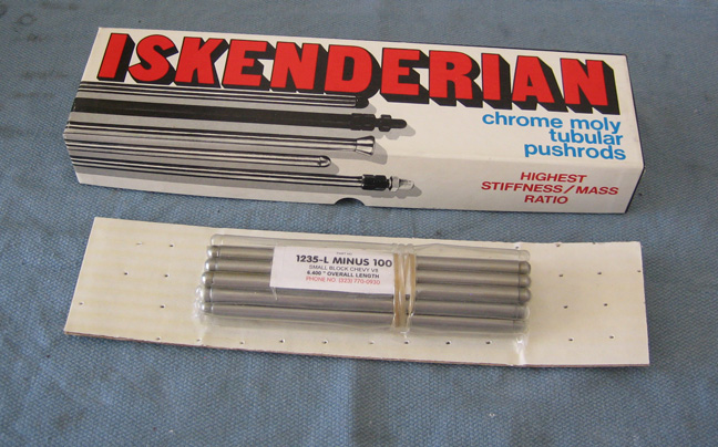
The length of my old pushrods were 6.500 long and the new ones that
you see below are 6.400 in length. If you look at the package, you'll
notice it says 'minus 100' within the number. The standard length for
Isky's numbering system for small block Chevy starts in the middle with 1235-L, which equals
6.500 long (my old ones). To make it easy for everyone, Isky either uses
a 'minus' or a '+' next to the number. You can get pushrods as long as
+.650 or as short as minus .400 in .050 increments. This makes it pretty
easy to dial in your setup like I had to.
Isky uses some good materials starting out with seamless heat treated
chrome moly tubing that is 5/16 diameter X .095 wall thickness. These
pushrods are also available in .080 wall thickness as well.
|
|
 |
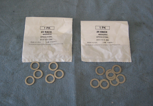
I used a .041 shim while testing (remember on the last
page) and things were pretty close with that one. But I knew when I used
some new pushrods that all bets would be off till I did more testing. I
bought two different shims packs, one was .032 thick and the other was
.005 thick. These are hardened steel shims and come in a pack of 25
each. I thought I'd be using the .032 shims but in case I needed a
little more, I could stack the two and make .037 if need be.
|
|
 |
|
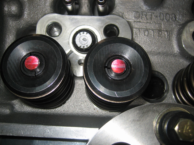
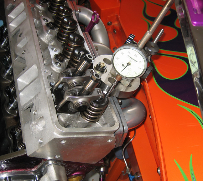
This contact area is right in the middle which is just what I was
looking for. How much shim did I use to produce this pattern? Well let's
just say I didn't expect to use the amount of shims that I did. Let me
explain how I got to this point.
With my new shorter pushrods installed, I started with .032 shims to
see how that pattern looked. That put the pattern very much like the
first one, over center, so it was time to try something thinner.
I went to the other extreme and didn't use any shim at all and that
put the contact area very close to the center. Now I could have stopped
here but I had one other thing that I wanted to try while I was at this
point.
With no shim being so close, I tried using .010 and that seemed to be
the sweet spot so that's what I went with. So what did I want to try?
|
|
 |
|
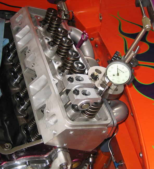
Note that my the old rockers are back on the engine here. What I'm doing
is checking my rocker arm ratio. Why? Well remember I was going to
revisit the geometry and rocker arm ratio thing? This is why I have my
old parts back on the engine. Let me show you what I've found. A small
block Chevy is known to have a 1.5 rocker arm ratio. And a big block Chevy
has a 1.7 rocker ratio. This is nothing new but I thought I'd start off
by stating this. When I was playing with the shims, different length
pushrods, removing and installing my new rocker arms, it got me thinking
about 'rocker arm geometry'. What I wanted to find out was...what ratio
does my engine really have?
|
|
 |
|
Checking rocker arm ratio is very simple, you need to find out how far
the valve actually opens and compare it with your cam lobe lift. Divide
the actual valve lift by the cam lobe lift and that gives you your
rocker arm ratio. So what did I end up with? See the first chart below.
I set the valve lash to .022 on every test and then did my valve lift
check. The actual valve lift would be a little more if I added my valve
lash to those numbers so keep that in mind for now. The 'Cam Lobe'
number is from my spec sheet.
The 'Intake' and 'Exhaust' numbers are what I measured with my dial
indicator (actual valve lift).
| Cam Lobe |
Rockers |
Shims |
Intake |
Exhaust |
Ratio |
| .430 |
Old |
N/A |
.627 |
.625 |
1.456 |
| .430 |
New |
None |
.605 |
.603 |
1.404 |
| .430 |
New |
.010 |
.611 |
.609 |
1.418 |
| .430 |
New |
.037 |
.613 |
.615 |
1.428 |
When I added in the valve lash, only one test came
out with the target ratio of 1.5 and that was with my old setup. The
one with the yellow above is the combination I ended up with. Now
this is far from ideal but I'm going to have to live with it.
| Cam Lobe |
Rockers |
Shims |
Intake |
Exhaust |
Valve lash |
Total lift |
Corrected Ratio |
| .430 |
Old |
N/A |
.627 |
.625 |
.022 |
.647 |
1.504 |
| .430 |
New |
None |
.605 |
.603 |
.022 |
.625 |
1.453 |
| .430 |
New |
.010 |
.611 |
.609 |
.022 |
.631 |
1.467 |
| .430 |
New |
.037 |
.613 |
.615 |
.022 |
.637 |
1.481 |
If you check out the 'Corrected Ratio' column you
can see what it would be if the valve lash was added to the
equation. Now all this was an eye opener for me and I was
disappointed with the result. On the other hand I can't do much
about it but found it very interesting.
|
|
 |
|
1
2
3
4
5
6
7
8
9
10 |