|
Road Trip
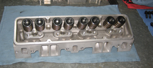
I took another ride with my good buddy Larry, to Engine Supply to
pickup my heads. They cleaned my heads, did a three angle valve job, new valve seals,
ground all the valve tips - which only took .003
to clean them all up, even the bad one. Those guys did a great job but found a few things wrong
which I'll talk about next. Also note the lack of rocker studs and guide
plates. I might not be using them any longer either which I'll talk about
more soon.
|
|
|
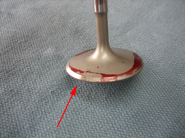
They did find one bent intake valve which had to be replaced. Notice the
surface that has been cleaned up (left side) vs the surface that hasn't.
The arrow shows you the mid point between the two. This meant that while
they were doing my valve job, they should have been able to grind off
all the red. And because the red still remains on one side means it was
running out of round and had to be replaced by a good one. I have no
idea how this ended up like this but it's good to know they took the
time and did the job right.
|
|
 |
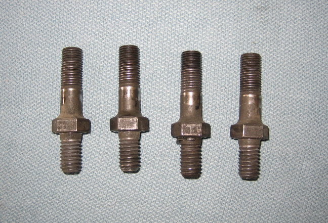
Here is another problem that was pointed out to me, my
rocker studs were worn out. Notice the area near the top that looks
normal. That area is how far my poly-locks (lock nuts) thread down to.
But the threads below that are all flat from my rocker arms rubbing
against them. Now the rocker arms have a smooth bore that rides on these
studs so how could a nice smooth surface do something like this?
|
|
 |
|
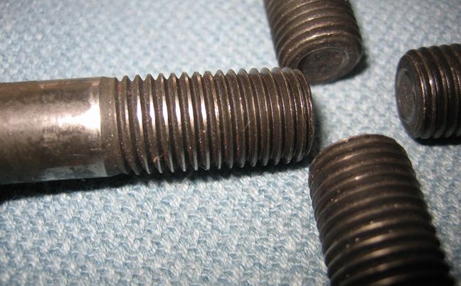
The reason is because of my stiff valve springs. My valve springs have
230 lbs. on the seat (when the valve is closed) and over 500 lbs. over
the nose (when the valve is open) so no wonder these studs are worn out.
These are my original rocker studs that came with my heads when I bought
them but the after market makes taller ones that have a longer shoulder.
By having a longer shoulder means the threads would be clear of any
movement of a rocker arm and would last much longer. The cost for new studs is one
hundred dollars.
I'll be needing some new rocker arms (being that my old ones are in
need of replacement) but the ones I have, which are made by Comp Cams
doesn't make that style anymore. They do make some even better ones that
take the place of my old ones and they cost 400 dollars. So it would
take five hundred dollars to replace these two items, so keep that number
in mind as we move on.
|
|
 |
New Camshaft
|
4-15-14 |
|
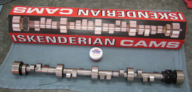
About a week later I received my new camshaft along with four roller
lifters. Boy does this new bump stick look good!! And to think that my
old one looked just like this at one time (hard to believe after seeing
my old one). This new cam has the same specs as my old one which is
something I thought about changing when I was talking with Mike at
Engine Supply. He had suggested going with a hydraulic roller in place
of my solid roller all in an effort to have softer valve springs.
I did think about it for a few days while he was working on my heads
and what I would need to buy if I went that way. New cam, all new
lifters (hydraulic), new valve springs, and I would need new rocker
studs and rocker arms. Would this new setup cost more? Yes. Would this
new setup be easier on parts? Yes again. Would I be able to rev the
motor as high? Not quite, but it would be close. Would it make as much
horse power? No.
Well there you have it, not as much power. This is why it was an easy
decision to go with my old cam specifications in place of a different
one. Why you ask? Easy, you can never have enough horse power!!
:-]
|
|
 |
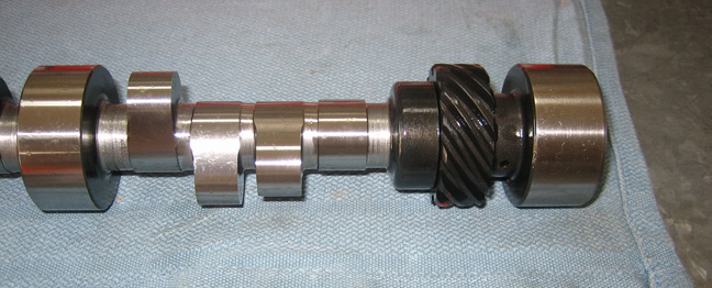
Here you can see the cast iron cam gear option that I choose to go with.
This was great news when I heard about it and I hope it works and lasts
like they say it will. It should last because after all, most cams have
this type of gear material and run with stock style distributor gears
all the time. I'm looking forward to not seeing anymore bronze
color material when I drain my oil in the future (think panning for gold
here).
|
|
 |
|
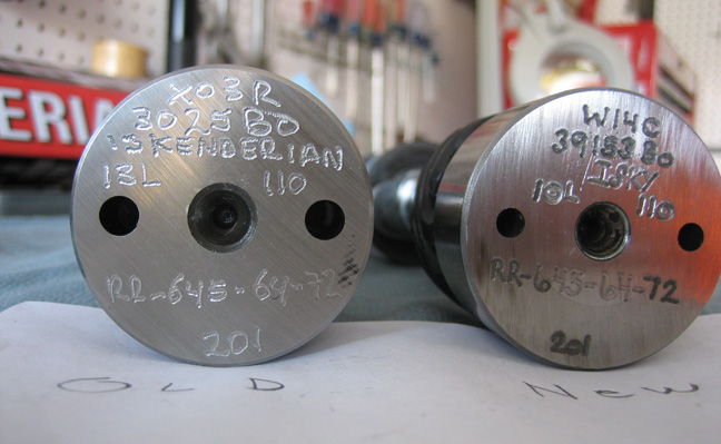
I took a quick shot of both cams for future reference
just in case I need it. Isky engraved the end with a part number, lobe
separation angle along with some other proprietary information.
|
|
 |
|
Degreeing in the Camshaft
Now that my timing set is installed, next up is degreeing the
camshaft. Degreeing a cam is something I did when I built the motor
years ago and I'll be doing it again here. The reason you would degree a
cam is to make sure it's installed the way it was designed by the
manufacture. What I mean is, camshafts are made on a production basis,
and sometimes things go wrong. If the cam you were installing were off
by a few degrees, it wouldn't work like it was designed to, and you
would be left wondering why.
All you need to degree in a cam is a degree wheel, a one inch travel
dial indicator, a pointer and your cam spec sheet. The cam spec sheet
will come with your new camshaft (at least it should) which you will
refer to as you're checking it. I own a dial indicator and a magnetic
base, made the pointer out of welding rod but the one thing I had to
borrow was the degree wheel.
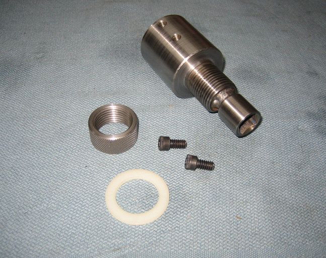
The degree wheel needs to be mounted on the end or of the crankshaft
(the snout) which is easy but you won't be able to use a bolt to hold it
on because you need to rotate the engine in both directions
trying to find top dead center. Going clockwise is no problem but
rotating the engine counterclockwise will try to unscrew the bolt
holding on the degree wheel. So what do you do here? Well I made
something that can do both, hold the degree wheel and roll the motor
over.
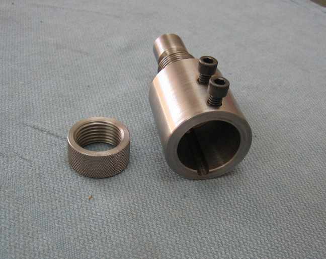
The degree wheel goes over the threads and is held on by the round
nut. I knurled the nut so it's easy to use without a wrench. The thread size
is 1"-12 X 1.00 long. The 1/2" square drive was a socket that I
sacrificed so I could use a ratchet or breaker-bar to turn it with. I
bored a 1/2" diameter hole X 1/2" deep pocket in the end of the adapter
to help line up the socket into. I put a large chamfer on one end of the
socket to give me a little more room for welding. Once everything was
where I wanted it, I welded the two together.
|
|
|
The other side is where it goes over the crankshaft and keyway. Once the
adapter is on the crankshaft it's held in place with the two 1/4-20
screws so it won't move while you're working. The plastic washer in the
picture above goes against the degree wheel so it doesn't get scratched
(remember I borrowed it) and everything worked very well for me.
|
|
|
|
1
2
3
4
5
6
7
8
9
10 |