|
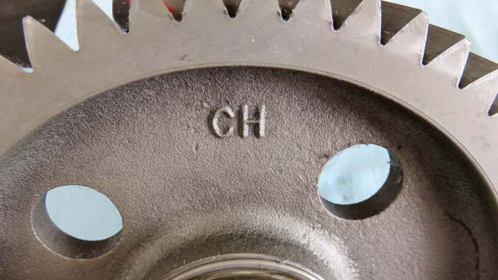
I came up with a plan for the base. What I'll be doing is using
this gear as is, but I'll modify a few things so I can use it. The
letters that you see will have to be removed but this is an easy
process.
|
|
 |
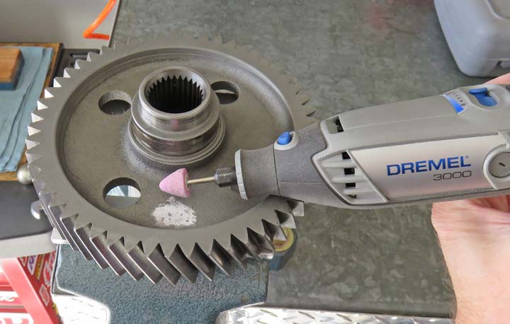
I used my Dremel with a grinding wheel to
remove the raised lettering which went very quick. The reason I'm
removing them is because I'll be attaching some blocks on this bottom
surface.
|
|
 |
|
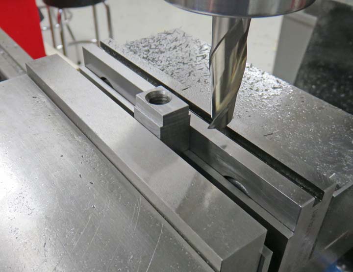
The Feet
Here I'm making some blocks out of steel. These pads (blocks) will get
welded to the bottom side and be equally spaced apart.
|
|
 |
|
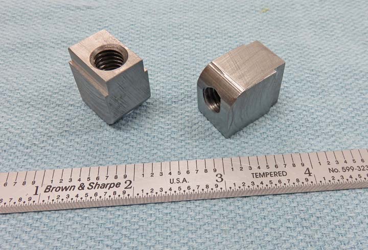
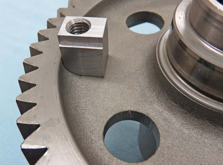
I made four of these steel pads and drilled and tapped
3/8-16 threads so I could attach some feet to them. I used a corner
rounding end mill to put a 3/16" radius on one side only, which will be
against the shoulder of the gear. The step at the top is to clear the feet that
I'll be using.
|
|
 |
|
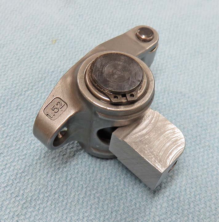
I'll be using some of my old roller rocker arms as feet.
And here you can see where the step on the steel pad goes. The rocker
arm is able to move once it's bolted to this steel pad and should sit
nice and level once they're attached.
|
|
 |
|
This should give you a better idea of how they will sit
on the gear. I left extra material on the top surface just in case I have to
trim a small amount off each one after welding. Heat does strange things
to metal so I'm just making sure I have some insurance.
|
|
|
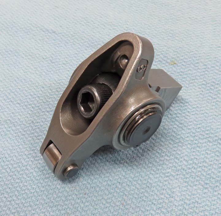
I'm using a 3/8-16 socket head cap screws to fasten the
two pieces together because the head of the bolt is round and sits below
the surface of the rocker arm. These rocker arms are designed to be used
with 7/16 diameter rocker studs but a 7/16 bolt diameter is too large
for this application, hence the reason for the 3/8 ones.
|
|
 |
|
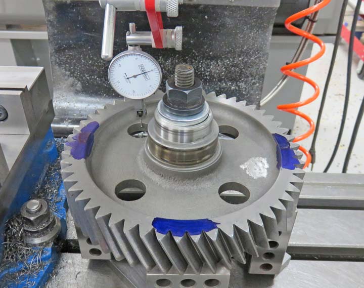
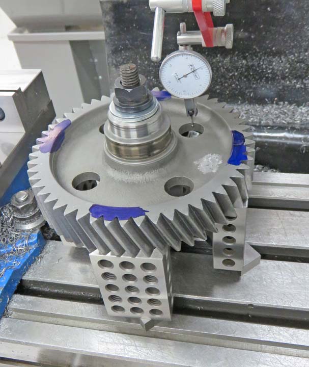
Layout I plan on equally spacing the steel pads around the
gear. And I want the pads to go between all of the holes. In order to do this I'll need to indicate two of the existing
holes to make sure they're in alignment. I started with the one that you
see below, then I'll move over to the one on the right.
|
|
 |
|
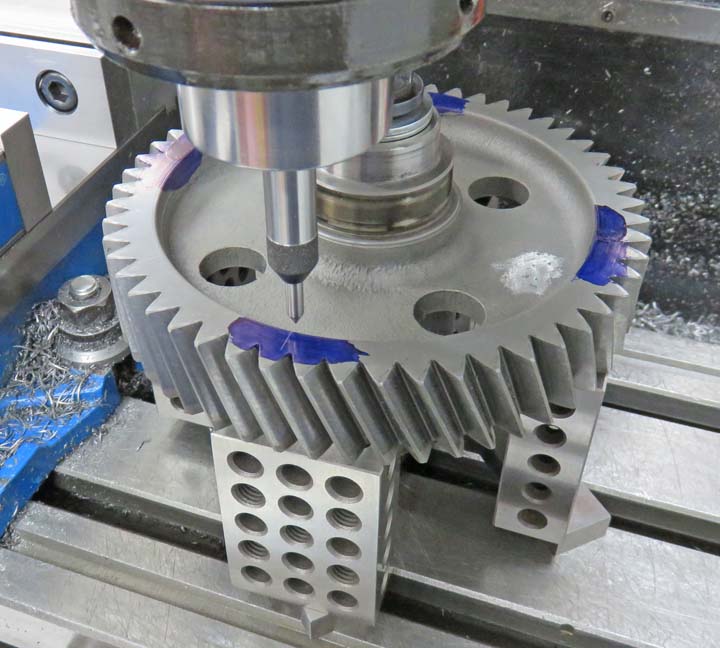
Now I'm at the right hand hole and have them both within
.001" of each other, which is plenty good. I then tightened down the
gear with the nut in the middle, indicated the round bearing surface
under the nut so I was in the center and and now I'm ready to layout
some lines.
|
|
 |
|
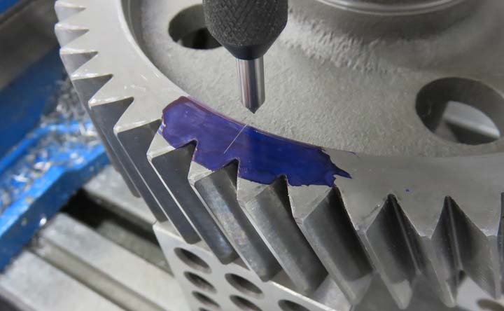
This is an unconventional way of laying out a line but
it worked for me. Why you ask? Well the pointer that you see is really a
tapping aid for threading because it's spring loaded. However, I'm using
the hardened point of it to scribe a line in some blue layout dye.
|
|
 |
|
All I did was move off center in both the X and Y axis,
lowered the spring loaded tip onto the surface of the gear and then
moved the mill table a small amount giving me my line. This worked great
and now I have a place to line-up my steel pads with.
|
 |
|
1
2
3
4
5
6 |