|
Here is a close-up of the slot. This worked out great and now it's time
to start on the lamp hardware.
|
|
 |
|
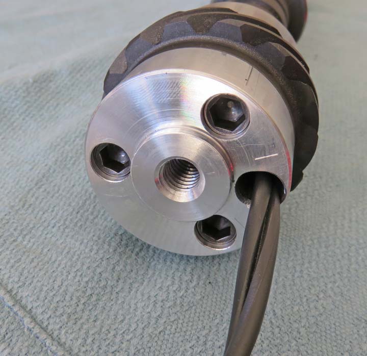
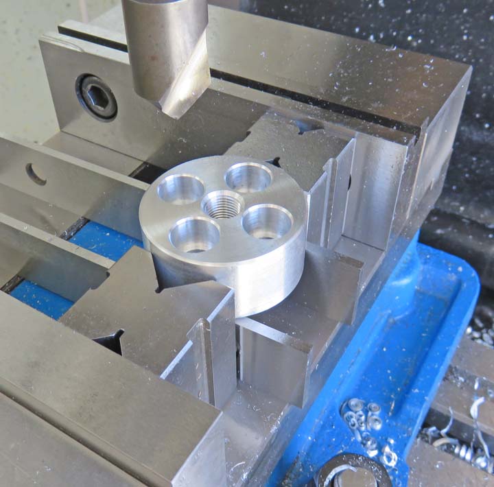
Back To The Adapters Here is adapter for the top along with the tight bolt
pattern. I counterbored the holes for socket head cap screws (shcs) but
they are smaller than normal. What I mean is, if I used a normal size
counterbore for a 3/8" shcs, they would have encroached into the
threads. So what am I going to use?
|
|
 |
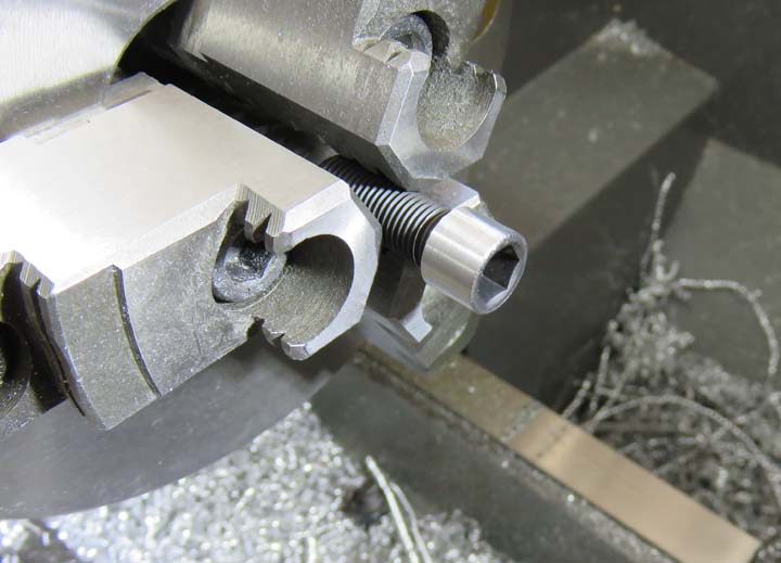
All I did was turn down the heads of these screws like I did the others.
They don't have to be that strong so this was a good option.
|
|
 |
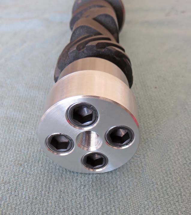
With all the adapter now made, the rest of the project should go pretty
fast.
|
|
 |
|
My Digital Read Out
I was thinking about all the holes that I've been
drilling to make my adapters, along with their bolt patterns and wanted
to show you a few things about my digital read out (DRO). This DRO does
much more than just tell me a number in X and Y, it can do many other
things as well.
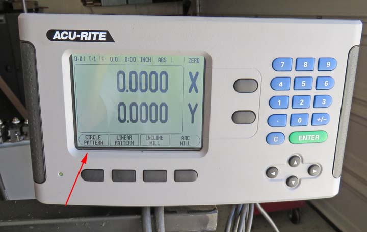
By pushing the right arrow button at the bottom-right
corner, this brings up the menu that you see below. I have many choices
here and one of them is "circle pattern" (arrow). I use this one to help
with drilling my holes. By pressing this button it brings up another
menu.
|
|
 |
|
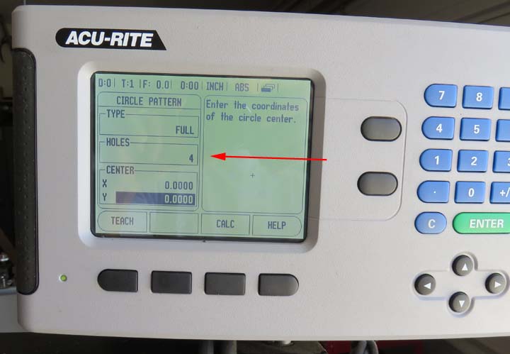
This next menu allows you to enter different parameters
to make a hole pattern. In the case of my last adapter, it had four
holes so all I had to do is enter the correct value into that area
(arrow). Below that you'll notice the X and Y values are both zero. This
tells the DRO that I'll be working around a center point.
|
|
 |
|
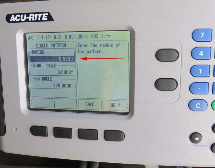
This is the same area but a different page. The value
that you see next (red arrow) is the radius of the bolt circle. I know
this is a weird number but this is what I had to work with because of
the two existing holes that were already in the cam. This is where I
drilled two more holes and then tapped them all for 3/8-24 threads. Once
I entered in this value, all you have to do is tell it the starting
angle (normally zero) and then hit 'CALC' which gives you the screen in
the next picture.
|
|
 |
|
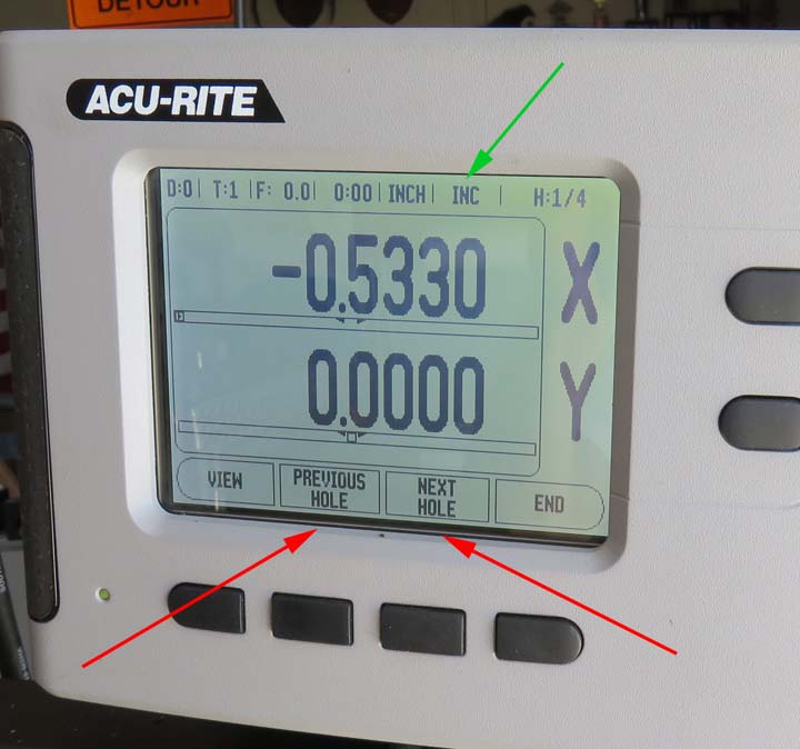
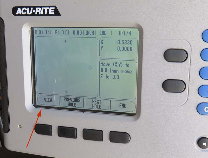
Another cool feature about this DRO, it's showing me
the direction and distance to my first hole. As I move the table in the
X axis, those numbers get closer to zero and once I'm at zero, I stop
and drill my hole. Also notice that the INC is showing now (green arrow).
This has changed from ABS (Absolute) from the previous screen to INC
(Incremental). This means I can move from hole-to-hole and still have my
original zero when I'm finished.
At the bottom of the screen you can see 'Previous Hole'
and 'Next Hole' (red arrows). Once I've drilled my first hole, I press 'Next Hole' and the DRO displaces a new set of numbers for me to
dial to.
This makes doing a bolt circle of holes a piece of cake. No more doing
and calculating or worse, if you have an odd number of holes you might
need to do some trigonometry.
|
|
 |
|
By pushing the 'View' button you can see which hole that
you're working on. And in this case you can see the four points around
the center with one that has a circle. This circle is the target hole
that's being displayed so you have a reference of which hole that you're
at.
Then once you're finished with all the holes, you push
the 'End' button and it goes back to the ABS screen (normal mode).
This is just one feature of this digital read out as it has many more but
this is the one I use the most.
|
|
 |
|
1
2
3
4
5
6 |