|
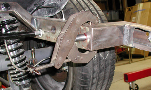
Here is the first one of the four to
be welded on. Now the first one was easy but lining up the others
weren't.
|
|
|
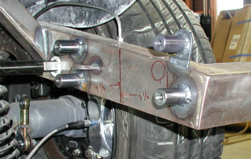
Here you can see all of them welded on
and ready for some bolts. The trick to lining up all the holes was done
one at a time. I drilled the hole in the brace on the box first and then
installed a bolt through it to hold the spacer on. This gave me the
location that I needed so things would line-up. After the two were held
together with the bolts, I clamped the assembly to the chassis and tack
welded the spacer. By doing this one spacer at a time, they all lined up
afterwards.
|
|
|
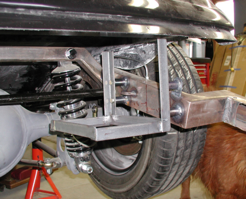
Here you can see how the box all
bolted up. Speaking of bolts, these are grade 8 fasteners that are being
used. Now this will all be covered later by a body panel. Well I had
planed to cut a hole in the trunk to access the battery from the top so
I needed to put the battery in place to mark some lines. Wouldn't you
know it, I missed the dimension by 1/8" and the battery wouldn't go
in. The hole in the trunk would have to wait till I could get the
battery in the box so out came the grinding wheel.
|
|
|
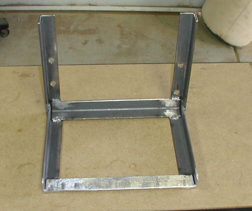
I removed the front lip from the angle
in front and smoothed out the rough edges. I have to say that this is
much easier to get that lead weight in there now. Because of the weight
of the battery hanging on just those two uprights, I needed to strengthen
things a little.
|
|
|
|
1 2
3 4
5 6
7 8
9 10
11 12
13 14
15 16
17 18
19 |